Vortex Relocation procedure
The atmospheric component of HWRF, WRF-NMM, needs ICs and LBCs to produce forecasts. The GFS and GDAS fields are used to create the preliminary atmospheric fields, which are further improved through the vortex adjustment procedures and data assimilation to provide the final IC to WRF. The vortex adjustment procedures are necessary because the initial vortex is often not realistically represented in the preliminary ICs since it originates from a low-resolution global data source, such as GDAS. Therefore, HWRF employs a sophisticated algorithm to adjust the vortex to match the observed storm intensity, location, and structure.This step can only be done after the successful completion of the init_gfs and init_gdas jobs submitted on earlier pages. If you have not already done so, please verify their successful completion.
Initial conditions for HWRF d02 and d03 are created by ingesting GDAS fields into the HWRF vortex initialization procedure. To prepare the fields for input in the vortex initialization, two 60-s atmosphere-only forecasts are conducted. These runs are referred to as the WRF Analysis and WRF Ghost runs, and their configuration is detailed in Chapter 5 of the HWRF Users Guide. Within the vortex relocation code, the fields are interpolated to the 3X domain, a temporary domain with 0.015° grid spacing. For historical reasons, some file names and executables use 4X when referring to the 3X domain.
The HWRF vortex relocation process has three possible stages, which are determined based on the intensity of the observed storm and on the availability of the 6-h forecast of the previous HWRF run. Figure 5.1 of the HWRF Users Guide describes Stages 1 and 2, and Figure 5.2 describes Stage 3. If the previous cycle HWRF forecast exists, and if the observed storm intensity is at least 14 m/s, HWRF is run in cycled mode. In cycled mode, the the 6-h forecast vortex from the previous HWRF cycle, adjusted according to the TC Vitals, is used for initializing the current cycle. If those conditions are not met, the HWRF initialization is a "cold start".
For a cold start of storms with observed intensity less than 20 m/s, the GDAS vortex is adjusted and then used. Conversely, for storms with observed intensity greater than or equal to 20 m/s, a bogus vortex is used. A cycled run will go through all the three stages, while a "cold start" run will go through Stages 2 and 3 only.
Stage 1: The previous cycle 6-h HWRF forecast is separated into environment fields and a storm vortex. This step is run only for cycled cases.
Stage 2: The preliminary IC generated by real_nmm and the WRF ghost and analysis runs is separated into environment fields and a storm vortex.
Stage 3: The storm vortex from the 6-h forecast from the previous cycle (for cycled runs), from the GDAS, or from the bogus vortex is adjusted to match the observed location, intensity, and structure provided by the NHC for the current time. Then the vortex and environment fields are combined.
Start by entering the wrappers directory:
Next, copy and edit the qsub template according to the example.
Finally, submit the job:
The relocate job should take approximately 60 minutes to run, but your runtime may vary.
If Stage 1 is successful, the standard out will say INFO: Stage 1 completed. For GFS the relocate runs at the analysis time. For GDAS it runs at each FGAT time.
If Stage 2 is successful, the following output files can be found in ${WORKhwrf}/gfsinit/relocate:
- gfs_env --> environmental fields from GFS data
- roughness2 --> sea mask and roughness length from GFS data
- storm_pert_gfs --> storm vortex from GFS data
- storm_radius_gfs --> storm radius information from GFS data
If Stage 3 is successful, the following output files can be found in ${WORKhwrf}/gfsinit/relocate:
- new_data_4x --> adjusted field on 3X domain when combined vortex + environmental flow is less than the observed maximum wind speed
- data_merge_d0[1-3] --> merged data on respective domains
A similar set of files can be found in the relocate subdirectory of each of the ${WORKhwrf}/fgat.YYYYMMDDHH directories.
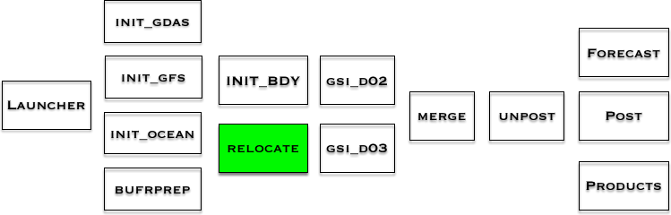
Where in the process of running HWRF?
This chart shows the workflow of the HWRF system. The green box(es) show the step(s) just completed. The components stacked together can be run simultaneously.